|
1962 Triumph TR4 Restoration |
|
Brian Sanborn, Groton, MA |
Putting the New Engine Together
Early on, the machine shop reported that the block and crankshaft were solid. The crankshaft had to be ground to .010 undersize. The head looked good on visual inspection, but the valves were badly recessed. That meant that the hardened seats were not only nice but required.
While We're Waiting
While I was waiting for the engine block to come back, I cleaned and examined all the engine parts. I was checking for obvious damage or severe wear. If the part looked OK, I measured it to see if it was still within the tolerances. These tolerance specs are printed in the workshop manual. Using this process, I found that the oil pump housing was out of spec and could not be rebuilt successfully. Finding a replacement was going to be difficult and expensive. I had already decided on a new set of pistons and liners, the camshaft was toast, and you should always replace the timing gears and chain on a major rebuild. The engine would need new valve lifters, camshaft bearings, rod and main bearings that were .010 oversize to match the cutting of the crankshaft. The head work would need new stainless steel valves, bronze guides and valve springs. The rocker shaft was badly worn beyond reuse and the rockers would need reconditioning to remove the indentation hammered in them where they contact the valve stem and the rockers would need new bushings and custom reaming to fit a new rocker shaft.
Shop for Parts
This was a major shopping list, around $1,500 in new parts alone. The problem I had not counted on was, that the major vendors, TRF and Moss, would be out of stock on most of these parts. I panicked a little and started polling the second tier parts folks. They are distributors of the big 3 or are independent suppliers and usually specialize in certain type parts. I found that BPNW (British Parts NorthWest) had almost everything I needed and their prices were very good. The bill came to $1,350 a 10% savings over the major vendors. But, I must admit I was a little concerned about sourcing such major important parts from someone other than TRF or Moss. BPNW doesn't have any computer order system, but they do have a friendly and helpful style and the parts they supplied were of good quality. I had the machine shop owner inspect them and he was impressed with the brands used and the quality.
Getting Started
The first part to come back was the block. I loosely fitted the upper shell for the new modern seal assembly because that would not be accessible once the block was on the stand. I needed to remove the plug that closed off the lower breather port. This was much more trouble than planned and I ended up mangling it on the way out. I used compressed air and a shopvac to clean out the metal filings from this mess. Everything must be kept very clean at all times. I checked the camshaft bearings that had been installed at the shop. They require a special tool to get the old ones out and the new ones in. I double checked that the oil feed holes in the bearing shells were lined up with the oil feed holes in the block. Stuff like this is critical. I assembled each of the pistons with new rings and gapped them to spec. I then installed the conrods to the pistons with new wrist pins into custom reamed bushings in the conrods. The conrods and caps are numbered and must be installed back into the same positions.
Install the Heart and Lungs
 The
next thing to do was to install the liners into the block. The area where the liners seal to the block must be
perfectly clean and smooth. I used Permatex High-Tack "purple" gasket sealer on the block and on the
figure 8 gaskets. It comes in a metal can with a brush applicator. These gaskets are made of thin metal and fit
into a groove for the two front cylinders and another for the rear cylinders. The liners are slid into the space
provided in a position that has them mate with the octagon shaped top surface of the next liner. When they are
all installed most of the big open space of the water jacket is now filled with the liner top edges.
The
next thing to do was to install the liners into the block. The area where the liners seal to the block must be
perfectly clean and smooth. I used Permatex High-Tack "purple" gasket sealer on the block and on the
figure 8 gaskets. It comes in a metal can with a brush applicator. These gaskets are made of thin metal and fit
into a groove for the two front cylinders and another for the rear cylinders. The liners are slid into the space
provided in a position that has them mate with the octagon shaped top surface of the next liner. When they are
all installed most of the big open space of the water jacket is now filled with the liner top edges.
The trick now is to keep them pushed down hard to make a seal and to keep them from falling out when you turn over the block. I made up 4 special tools that copied the custom tool shown in the workshop manual. I used a short section of black pipe and some large grade 8 washers. Using the head bolts you position the special liner clamps over the stud bolts between the first and second cylinders and the third and fourth cylinders. These clamps should be kept in place until the head goes on.
The crankshaft can be fitted now. Turn the block upside down on the stand. Lube everything up with lots of special engine assembly oil. Fit the upper main bearing shells on the block checking to see that the oil feed holes line up. In my case, the rubber and spring rear seal has to be installed on the rear of the crankshaft and the special grease installed in the groove of the aluminum seal upper assembly. If you are still using the older scroll seal, you need to align it with a special tool and bolt down the two halves before installing the crankshaft.
The crankshaft is the heart of the engine
Lay the crankshaft very carefully onto the 3 main bearings. Turn the crankshaft to make sure everything moves like butter with no rubbing sounds. Next the thrust washer bearings are inserted between the center main bearing journal and special surfaces on the side of the crankshaft bearing surface. The front to back end play needs to be checked for spec and if there is too much, the thrust washers need to be swapped for a larger size part. You should now insert the lower bearing shell into each journal cap and making sure the numbers on the cap line up on the same side as the numbers on the block. By the way, if everything is normal in your engine the numbers on the block and the numbers on the cap should be the same, If not the engine parts are not original and could be a problem since the block and caps are precision line bored at the factory and are intended to remain as a set. Slobber up with assembly lube and install the center cap with the lower thrust washers in place and front caps and tighten lightly. The rear cap takes some more work. It is a tight fit and must be shimmied down with a rubber hammer making sure the rubber seal slides into the groove in the lower seal assembly. Tighten the bolts down lightly just to seat the caps. Spin the crankshaft. It should move freely and smoothly with no hint of play or drag.
Fill the holes with new pistons
Next we can install the new pistons. Spread assembly oil everywhere. You need a ring compressor to push the new rings into their grooves in the pistons... so that the whole thing will fit into the liners. Check the numbers for the right cylinder and slip the first piston into the liner being careful not to bang anything up against the block. This is best done with the block over on its side on the stand. Line up the crankshaft to get the best position for installing the bearing shell on the conrod and slip it into position on the crankshaft journal. Be sure to use lots of assembly oil and line up the oil holes. Install the lower bearing shells on the cap and slip it in place. The conrod bolts can now be threaded into place. Lightly tighten and rotate the crankshaft to check for smooth operation. Repeat this process for the other three cylinders. You now have the heart and lungs of the engine assembled.
Installing the Camshaft and Timing the Engine.
The first thing that needs to done is to reinstall the engine front plate. Be sure to use a new gasket and gasket dressing. This goes behind all the timing gear stuff. The camshaft should be buttered with assembly lube and carefully slipped into the block. You have to support the cam as the journals slide into and past the bearings in the block. Reinstall the front camshaft bearing and lightly tighten things up. The cam should spin easily in the block. If not, figure out why not before going any further.
Installing the timing sprocket gears is a very time consuming and confusing process and must be done correctly. This is the basic brains of the engine. If done correctly the valves will open and close at just the right time and the engine will purr. I refer you to the Haynes manual for a detailed procedure. When you have finished you will have the two timings gears and the timing chain installed. The timing chain tensioner and the timing cover can be installed now. Replace the front oil seal in the timing chain cover before installing.
The rest of the little bits
The front hub can go on next. I took the hub and pulley apart for cleaning and painting. I also filed notches in the pulley edge at 0, 4, 8, 12 and 16 degree points and filled them in with yellow paint. This makes timing the engine a little easier. The fan can be bolted on now with new rubber isolators.
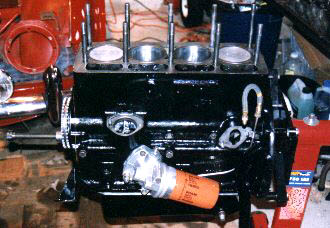
Before turning the block straight up, finish up by installing the oil pump and strainer. The inside of the oil pump should be filled with the thick assembly lube to ensure that the pump will prime. The oil pan is next. Be sure that the mating surfaces are clean and smooth. Check the area around the bolt holes to see if they are still flat. I used Permatex Hylomar gasket dressing here and throughout the engine assembly. It is a tube of blue sticky stuff that does not harden and the parts can be separated later without the gasket being destroyed. It must be used very sparingly to avoid getting any squeezed into the interior of the engine.
Make sure all the oil gallery plugs are installed with their appropriate washers. Install the oil filter housing in place. I elected to fit a spin-on oil filter adapter. Fit the oil pressure pickup line with the special copper washers. You must re-anneal the washers or get new ones to get a good seal. Using a new gasket, install the fuel pump. I had to also install the new breather siphon tube.
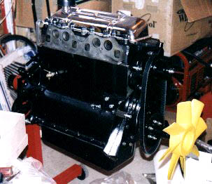
The head goes on next
 Now
we can turn the block straight up and remove the liner clamps so we can install the head and rocker assembly. Reinstall
your head studs if they were removed or needed replacement. Before going any further, install the solid valve lifters
with lots of assembly lube. Prepare the head by cleaning all the surfaces with mineral spirits. Absolute cleanliness
is needed. You may want to scrape out all the stud holes in the head. Crud collects here and will fall out and
dirty the gasket when you fit the head. The copper head gasket should be prepared with a liberal coating of spray-on
Permatex copper gasket sealer. Let the sealer set and then position it on the block. I turned the block to the
70 degree position to be able to see that the gasket was still clean and in position as the head is moved down
the studs. Use the rubber mallet again.
Now
we can turn the block straight up and remove the liner clamps so we can install the head and rocker assembly. Reinstall
your head studs if they were removed or needed replacement. Before going any further, install the solid valve lifters
with lots of assembly lube. Prepare the head by cleaning all the surfaces with mineral spirits. Absolute cleanliness
is needed. You may want to scrape out all the stud holes in the head. Crud collects here and will fall out and
dirty the gasket when you fit the head. The copper head gasket should be prepared with a liberal coating of spray-on
Permatex copper gasket sealer. Let the sealer set and then position it on the block. I turned the block to the
70 degree position to be able to see that the gasket was still clean and in position as the head is moved down
the studs. Use the rubber mallet again.
You can now torque down the head to 105 ft.lbs. using the method in the workshop manual or Haynes. Place the new pushrods in place riding in the valve lifter. Assemble the rocker assembly with a new rocker shaft and rebushed rocker arms. Place the rocker assembly on the head, making sure each of the pushrods has engaged the tip of the rocker ball. The rockers should be to a .010 clearance.
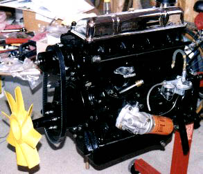
We can finish up for now by installing the rebuilt or new water pump and thermostat housing. Install the rubber overflow hose. Don't install the heater pipe yet, as it can be damaged while installing the engine.
Waiting to be installed in the car